Further History of Six
Monday, March 1st, 2010David Bliss continues the story of his restoration of a 1906 Rover 6hp, which began in the December issue. Some useful insights to anyone who has to have parts made from scratch!
Published in Freewheel, April 2005
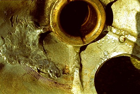
The 1906 6hp restoration took me six months of continuous work, encountering and solving numerous problems on the way such as getting poor quality, ninety year old cast aluminium welded and learning how to balance a single cylinder engine. The balancing problem was one I had never thought of until that point, how can you possibly achieve a balance when there is a constantly varying mixture of rotating and reciprocating motion involved? The rule of thumb solution that I learned came close to perfection.
When I put the car on the road in the spring of 1998, drivable but not yet finished, I thought the major problems were behind me and that from then on I would coast on down to the finish. How wrong could I be! The events of the next three years were to test my patience to its limit. The bad advice and poor workmanship of a number of supposedly well qualified ‘experts’ resulted in the use of wrong materials and in items having to be made again, at a great cost in both time and money.
One problem for which I did not need ‘expert’ assistance to solve nonetheless took a great deal of time and experimentation to sort out. When I bought the car it was fitted with a 1905 Rover carburettor that was not the correct one for the 6hp and not really suitable. Someone somewhere may have the correct Rover carburettor in their collection of spares, but I found a very early multi-jet Zenith that would fit and could be modified to suit the engine. Some alteration to jets and choke size (not the sort of choke used for starting) was needed. Using experience built up over many years and some experimentation these adjustments were made. The results seemed very satisfactory until the day we got caught in a sudden thunderstorm. Although we have no weather protection, my daughter thought this amusing at first, but then rain turned to hail and shortly afterwards, just yards from home, the engine stopped. Water had got into the electrics but worse was to come; when the car dried out I found that the engine would not idle.
To get at the slow running jet it is necessary to remove the emulsion tube. This tube was completely encased in fine grit and was blocked. The carburettor is mounted low down, under the floorboards on the passenger side. It was in line with the spray of grit-laden water thrown up by the near side front wheel. I was horrified, even in that short time the grit could have gone through the engine. Luckily there proved to be no damage to the piston or cylinder, although the valves and seating were dented. I needed to go back to the drawing board to find some way of stopping this happening again. The first thing I tried was fitting a cowl; this was no good, dust still found its way in over a period of time. Fitting a filter caused the air to bounce so that when the throttle was opened air and fuel was being spat out as much as in. This was all very disheartening, especially as the car had run so well initially. Eventually, however, with a great deal of thought and experimentation, a satisfactory solution emerged.
All my engineering knowledge and skills are self-taught; I am dyslexic and have no formal qualifications. Because of this, before I machine any parts, I have to think very carefully through the procedure and check and recheck measurements to ensure a satisfactory outcome. There were some parts for the Rover that I could not make with the equipment in my workshop, so I had to go to the professionals. The next five firms that I entrusted work to failed to produce anything satisfactory. In one case I was able to retrieve the situation myself, but the rest of the work ended up in the bin.
One of these firms was to make new stub axles, copying the originals. As they were better equipped to measure the originals accurately, I left it to them to do everything necessary. Two months later I had not heard from them, so I called in. They had just started machining my new stub axles. I was very impressed with the huge billet of EN24 steel they were using (£500 worth), but not their planned procedure. I could foresee that further down the line it would be very difficult to position the holes for the steering arms accurately. I voiced my concerns to the man who was machining the basic shape, but he brushed them aside, saying that the man on the milling machine would not have a problem. I remained unconvinced, and asked a precision engineer if he could measure the stubs when they were finished.
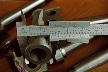
In the event, I did not have to bother him. The new stub axles were visibly out, using just a surface plate, set square and vernier calipers on my kitchen table I found errors up to 60 thou. on important dimensions.It is possible to see in the photograph where the holes for the steering arm have broken through into the king pin hole (they are 0.072 inches out), and these are pilot holes! There is still a taper to machine out, which would then cut into the king pin hole by about 0.050 inches
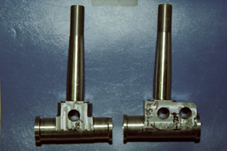
The reject stub axles. The initial turning was good quality, but there was a lack of understanding of how to accurately position the holes.
The stubs had to be binned and the firm declined to try again. Their excuse was that they usually worked from drawings! If they needed drawings why did they not say so or make them? Time was now running short; the new motoring season was fast approaching. Luckily a local engineer came to my rescue. His firm makes parts for historic aircraft so their work has to be absolutely accurate. His method used much less metal and the overall cost was far less than the first firm would have charged for the metal alone.
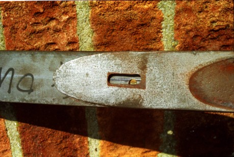
The badly posisioned hole in the new top leaf springs. The hole is nowhere near the centre of the slot in either direction.
At the same time I had sent my rear springs off to have new top leaves made, as one of them had cracked. When they came back I could not believe that they had drilled the holes ⅛″ off centre. The firm did finally agree to make new leaves, but were not happy when I asked them not to drill the holes, they told me that I wouldn’t be able to drill the holes myself. However, some years ago, one of my hobbies was restoring antique firearms, including making the springs, so I could confidently inform them that I could machine a hardened spring and that if the spring was too hard to machine it was also too hard to be of use, it would break. I also decided that it would be a good idea to put an extra leaf in each spring and made these myself out of springs from a 1950 Alvis TD, this involve machining slots, which had a total length of more than 4 inches. I did this using an ordinary milling tool; the trick is to use a very slow speed (about 100 revs). Coincidently, these springs were made by the same firm, Woodhead of Leeds, that had made the original Rover springs in 1906. The firm only closed down a few years ago.
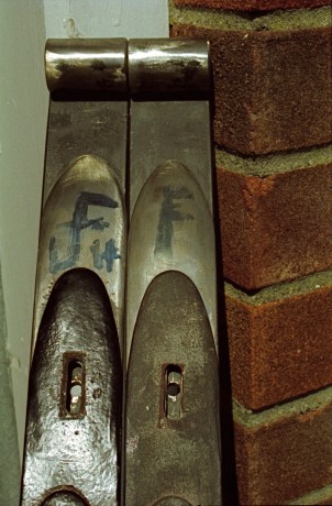
Springs are too hard for me to drill? Not only have I drilled the holes accurately but I have also machined a slot in the each of the second helper leaves which I made from an Alvis TD car spring. You can just see the edges of these slots through the slots in the original leaves.
The next setback was nothing to do with workmanship, but may have been divine retribution for pranks I had played on our farm cats as a boy. In 1999 we sold our farm and my brother’s two cats came to us as temporary boarders until renovation work on his new home was completed. One of the cats tried its claws out on the recently upholstered seat. I rang the upholsterer and asked him if he could repair the seat and put the skin back on the cat! Both cats had frequently used tractor seats as beds and never done any damage, maybe new leather was more tempting.
In 2000 I sent my rear wheels to have new rims and felloes fitted because the original rims had rusted badly and were very thin and cracking. After only three months the rebuilt rims had loosened as the wheelwright had taken too much off the ends of the spokes. I had to make a special bush to tighten the spokes back into the felloes, which is not really to be recommended but does work if done properly. I feel very saddened by such poor workmanship, especially as in over ninety years the wheels had only loosened slightly. They knew how to make them properly in 1906.
At the end of 2000 metal was visible in the oil in the back axle. This came as no great surprise as I knew that the pinion had, at some time, been wrongly fitted, severely damaging the teeth. I had thought the rectification work I had done would last a long while, but no such luck. The crown wheel is 11 inches in diameter and less than ⅜ inch thick so it would be very difficult to remanufacture, and correspondingly expensive. I decided that I would just replace the pinion, and took it to a Norfolk firm who said it would be no problem, ‘like shelling peas once the machine was set up.’ To reduce the cost I made two blanks for them to machine, at least one should have been right. In the end the firm made six attempts before giving up. I had to find someone else to do the work and, luckily, I rang Llewellin’s Gears in Bristol. I arranged to take my crown wheel and pinion down to them to discuss the job, I also took the first firm’s attempts to show what had gone wrong. Llewellin’s really did know their business, I learnt that the Norfolk firm had got the profile correct but used the wrong machine settings and that they had also used the wrong grade of metal, the gear would not have been tough enough.
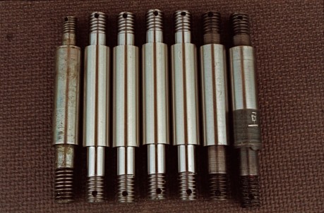
I thought I could relax a little while I waited for my new pinion. I needed four new pins for the differential, but they seemed fairly straightforward to make. Little did I know that two firms were going to do their worst with these pins, which hold the complete differential housing and crown wheel, taking all the drive thrust. One pin had already been broken and repaired at some time, but there had been some movement. I decided to increase the small end of the pin from ⅜″ to ½″ in diameter (some time later I was given a very late 6hp axle and discovered that Rover themselves had made this modification and that they had also made all the other modifications to the axle that I had made to mine). I needed to know what metal to use for the pins, which I knew were glass hard as I could not file them. I went along to a local firm of precision engineers, who sent me to a heat treatment firm to get them tested. They told me that they were 45 hardness so I should to use EN 24 and have it induction hardened. The figure of 45 seemed low to me, I used to use plough parts with 250 to 600 hardness, but I was told that would have been the old Brindell hardness test, the 45 was a different test. As I have not got a cylinder grinder I asked the engineering firm to machine the pins. I gave them drawings showing the tolerances, mostly –0, +5 thou., the machining should have been a simple job, no chance of mistakes. When I got them back they were nowhere near my measurements, the most critical distance, the length between shoulders, was –30 thou. The firm apologised and said they would make some more.
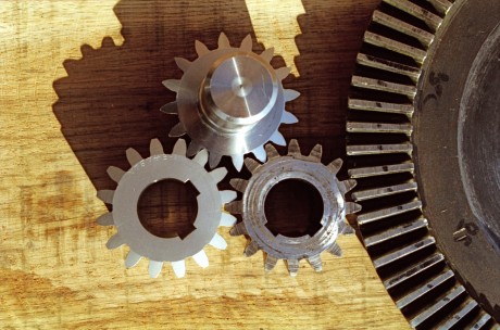
Pinion gears next to the crown wheel. Top: The incorrectly machined blank. Lower right: The original gear Lower left: The perfect copy from Llewellin's
The new pinion gear then arrived back from Llewellin’s’, beautifully made and with a guarantee of workmanship and materials. Two days later I got my pins. I had decided to have five made in case there were any problems during the hardening process and, sure enough ,one had partly melted but the others looked OK. I tried the differential gears on the pins and noticed that they tended to stick, showing high spots, and that the gears left score marks on them. Unlike the originals the new pins were easily filed. I went back to the heat treatment firm, who repeated their test, coming up with the result that the new ones were harder that the originals, 47 instead of 45. Whatever the test showed, the new pins could be filed the old ones could not. I decided to ask Llewellin’s for an opinion.
I rang Mr. Horlick at Llewellin’s and told him of my disappointment over the pins. He asked me to send both old and new pins to them for testing. These tests showed what had happened, the first test had not been done properly, they had punctured the case hardening and measured the core hardness. The correct figures should have been 60 case and 45 core, the new pins were 47 all the way through. I asked Llewellin’s if they would make pins for me, which they did. These pins were exactly to the measurements I had given, they had not needed the tolerance limits I had given. This is workmanship as it should be! Mr. Horlick also said that if I did have to replace the crown wheel his firm could make the gear by making it thick enough to prevent it warping during quenching then machining off the surplus in the hard, thus eliminating the need for the type of muffs that would have been used in the manufacture of the originals.
Since the rebuild the car has covered over 3000 miles with no signs of trouble.
Great post, I bet a lot of work and research went into this article.